Building a microcontroller based sensor for my yacht appeared to be an easy task. During last year I have learned a lot and thought it would be nice to share some ideas.
From InfluxDB to SignalK
My initial choice for an architecture was InfluxDB. It appeared to offer everything you would want:
- Installable as an Docker image
- Lightweight enough to run on Raspberry Pi
- A large variety of diagrams to choose from
- Library to ESP8266 (Wemos D1 mini)
At this point the SignalK server and SensESP looked like too complicated and bloat for me. However, after following my tinkering for the first season my co-founder wanted something more professional-looking. He was also worried that a 100% DIY project would be a problem when we had to look for a new owner to our boat.
It took me a while to get myself familiar with the aforementioned framework. I even tried to write my own implementation of the SignalK client for ESP8266. Finally I gave up and did a showcase of some SensESP sensors producing random values and SignalK server with the default Instrument Panel. That did the trick.
Finding a Decent Case
Building the first sensors on the breadboard was an easy task but finding a decent case was harder than you could think. After playing with the first prototypes I came up with the following list of requirements:
- The case should be waterproof(ish) and durable enough to survive the marine life. Our engine room is theoretically dry but there is always moisture on the boats.
- No rusting metal parts. The screws (if any) should be plastic or stainless steel.
- There should mounting lugs for wall mounting. It is not acceptable to mount the sensor by drilling the through its bottom as the circuit board must be removed to access the holes/screws.
- There should be enough space for connectors.
- No matter how nice over-the-air updates you might have at least I definitely have to have an easy access to the microcontroller. The housing should be easily opened.
- Clear case would show the LED signals and help troubleshooting the sensors.
- As we’re communicating on wifi it is best to avoid aluminium cases.
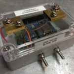
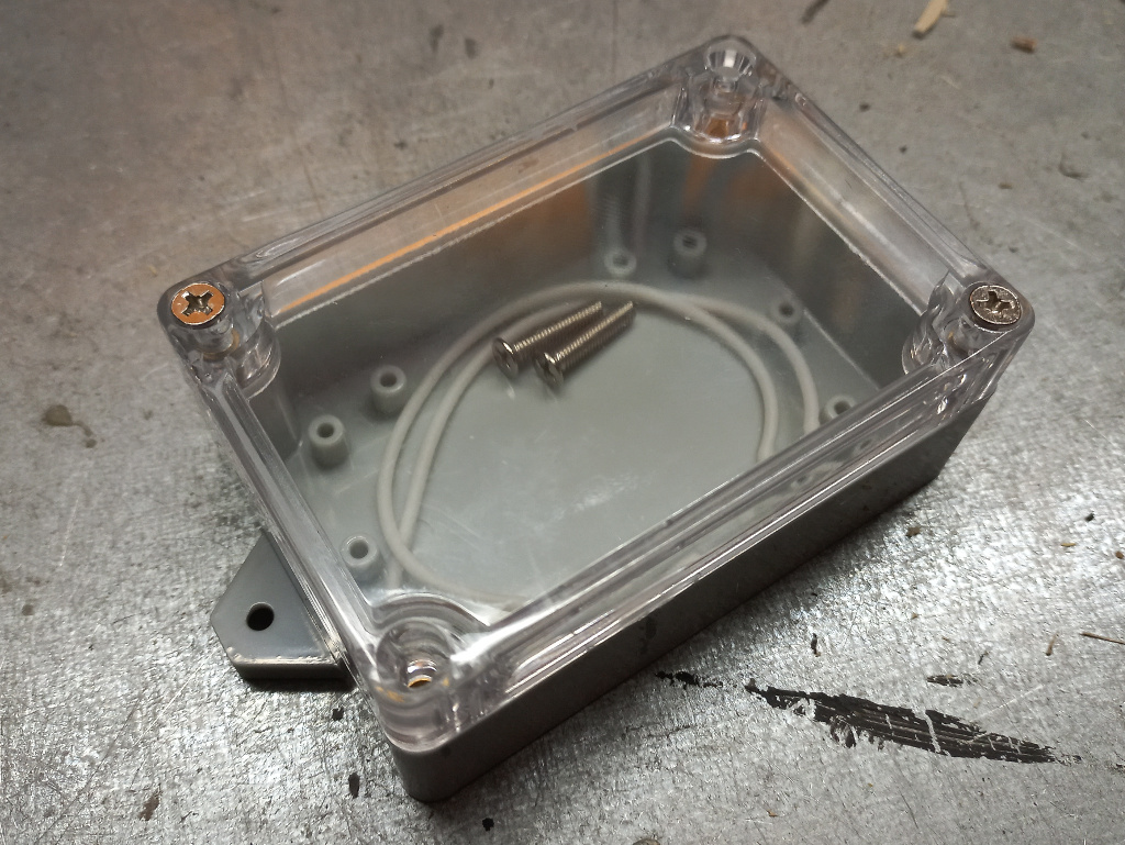
I tried to find a proper housing from the local electronics webshops and purchased some promising cases. Typically the screws securing the cover were in the bottom. In the prototype (well, it was supposed to be a production version but…) shown in the picture the I replaced the original screws with stainless steel threaded rods and nylock nuts. It worked all right but was a bit too laborious.
Finally I managed to find cases I had been looking for. I ordered one larger and one smaller box for and start. It turned out that they satisfied all my requirements.
Powering the Board
My first idea about powering the sensors was to build a old-school voltage regulator LM7805 in each of the devices (see this blog post for an example). With this I could use the yacht’s 24V DC and possibly avoid some wiring.
However, I soon found out that this cause me a lot of work and increased the risk for mistakes in soldering. I actually fried some capacitors when making this!
The next level in this path was to order an adjustable voltage regulator component from Asia. I bought a bag of these from Aliexpress but they turned out to be crap. Or maybe I could not install them, you never know.
These setbacks made me think of alternatives. I had noticed that still engineered a 24 V power cable to each of the sensors so I could power off the devices if required. My hope of somewhat utilising the existing power cables did not prove to work. Distributing the 24-to-5 DC-DC step-down made the sensors more compilated, large and prone to errors than installing the 5 V power network for the sensors.
Finally I ordered a DIN rail installable DC-DC converter which gave me a stable five volts. It even has short circuit protection which has saved me a couple of times.
Connectors
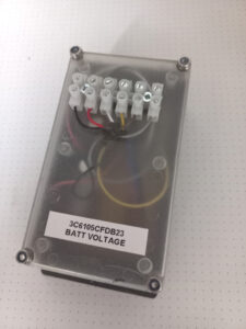
In the very first experiments I drilled a hole to the housing and connected the wires to screw terminals on the board. While my goal was build the sensor at home and spend minimal time onboard installed the screw terminals outside the housing as can be seen in the early prototype above. This proved to be functional but required manual steps which I wanted to avoid. You have to drill holes for wires and screws securing the terminal bar and use a silicone to seal the holes. Especially the latter was time-consuming and messy.
I tried to find waterproof connectors which I could use but they turned out to be hard to find. As I wanted to housing cover to be as removable as possible without any wirings the connector should be small enough to be installable to the bottom part of the box. Again, if I had connectors to gauge and power I would need two connectors which would mean more soldering and drilling. I would have to solder tiny connectors onboard which I wanted to avoid as much as possible.
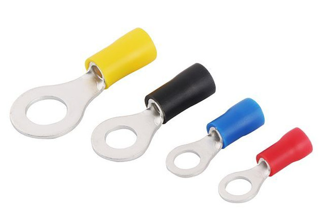 My current solution is to use stainless steel screws going through the housing. The wires both inside and outside have ring terminals. To secure the connection I solder all connectors to their wires.
While I don’t have long lasting experience of the solutions it appears to be quite nice at least to install. The Abiko connectors are widely available, robust and easily installable onboard. The screw terminals allow me to attach multiple wires to them. I can chain the power lines from sensor to another or use common ground or power for sensor and gauge (e.g. the Hall sensor for revolution measurement).
Building a Current Sensor
In this example I’m building a case for a current sensor. It has Wemos D1 mini with ADS1115 powered by SensESP firmware. The circuit board is made by Aisler. I have made sensors with prototyping board but again, there are a lot of soldering and tinkering which may break in the marine environment. While the Aisler prices are ridiculously low I wonder why bother.
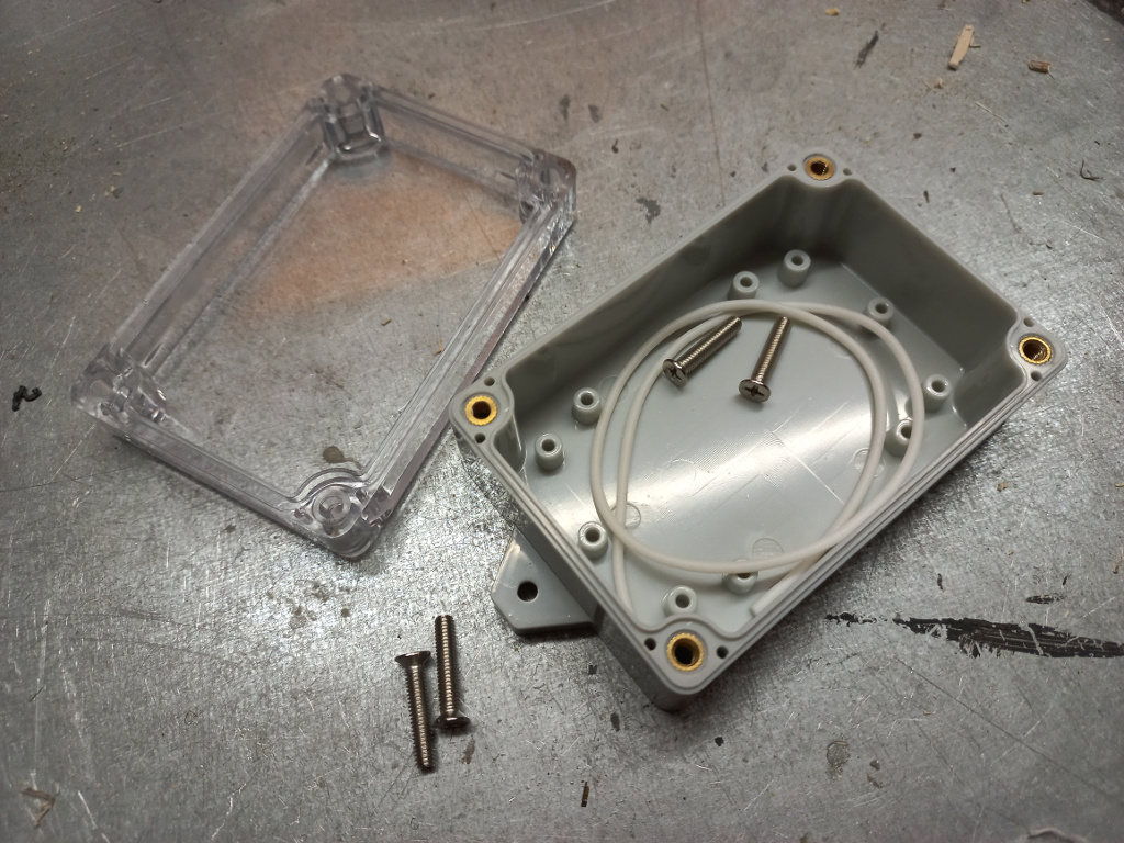
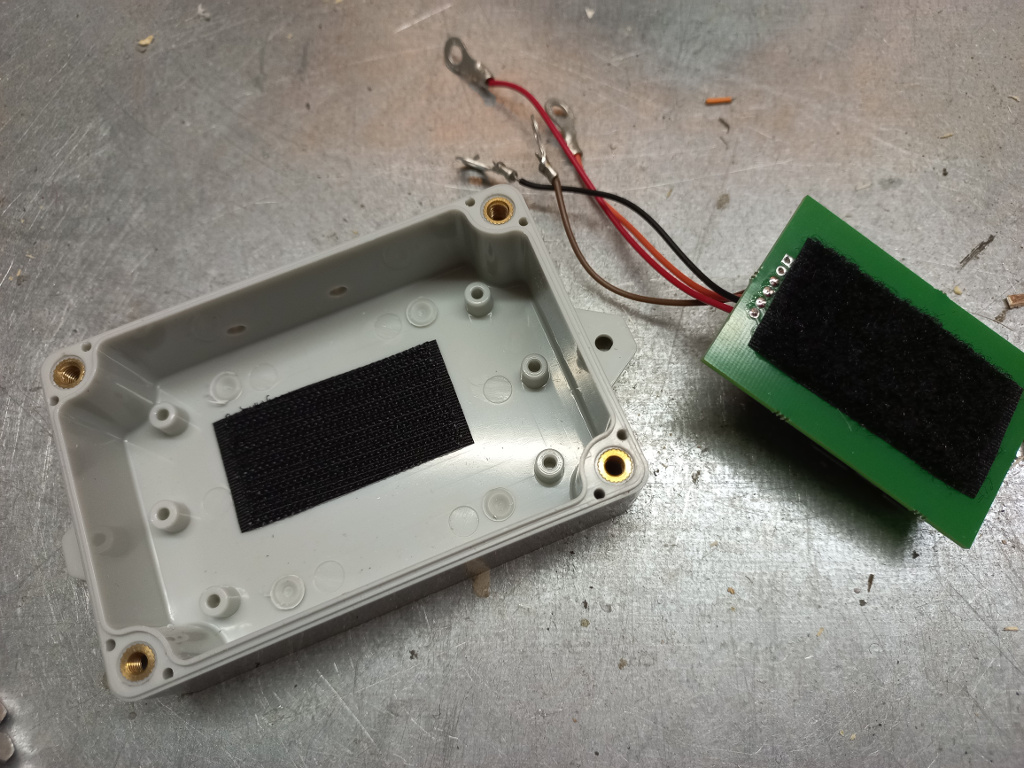
The abovementioned cases look looks this. The white strip is for making the case waterproof. There is a groove on the cover for this.
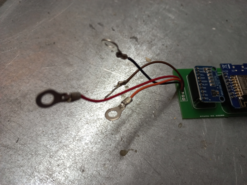
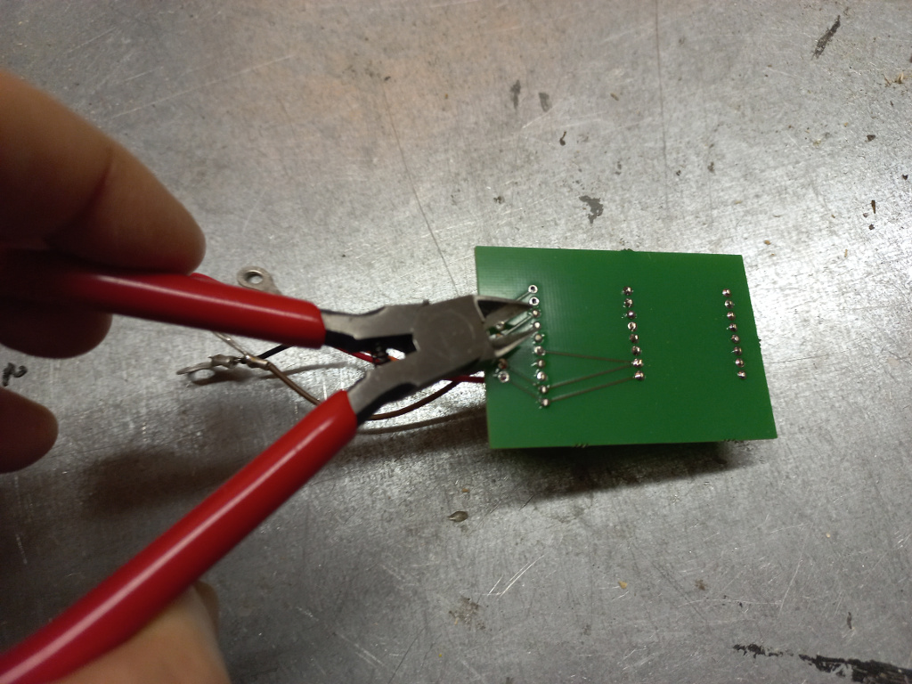
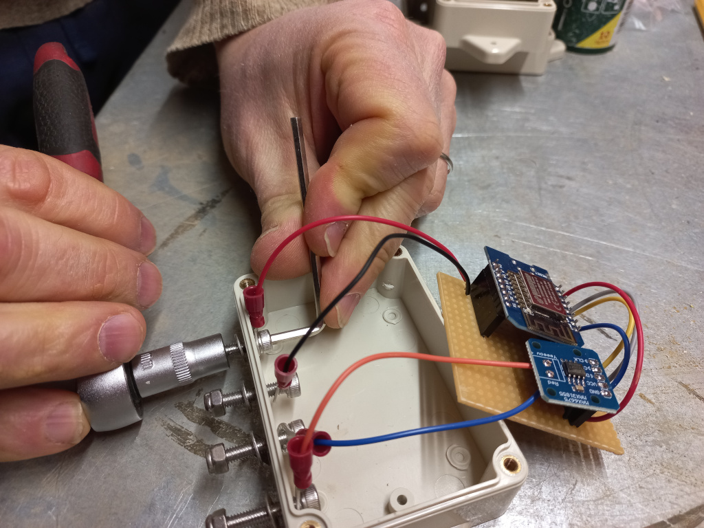
All the wires connecting to the circuit board have ring terminals. The wires are soldered to the board. I avoid using screw terminals to avoid the risk of loosening connections.
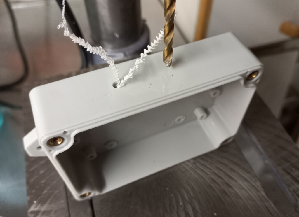
The housing has seats for the screws. As I don’t need them I drill them away.
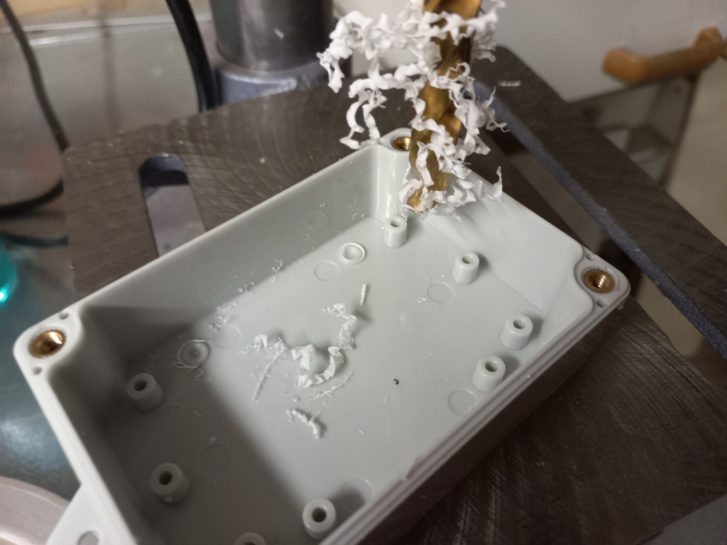
Drilling holes for the connector screws. I use 4 mm drill for M4 screws.
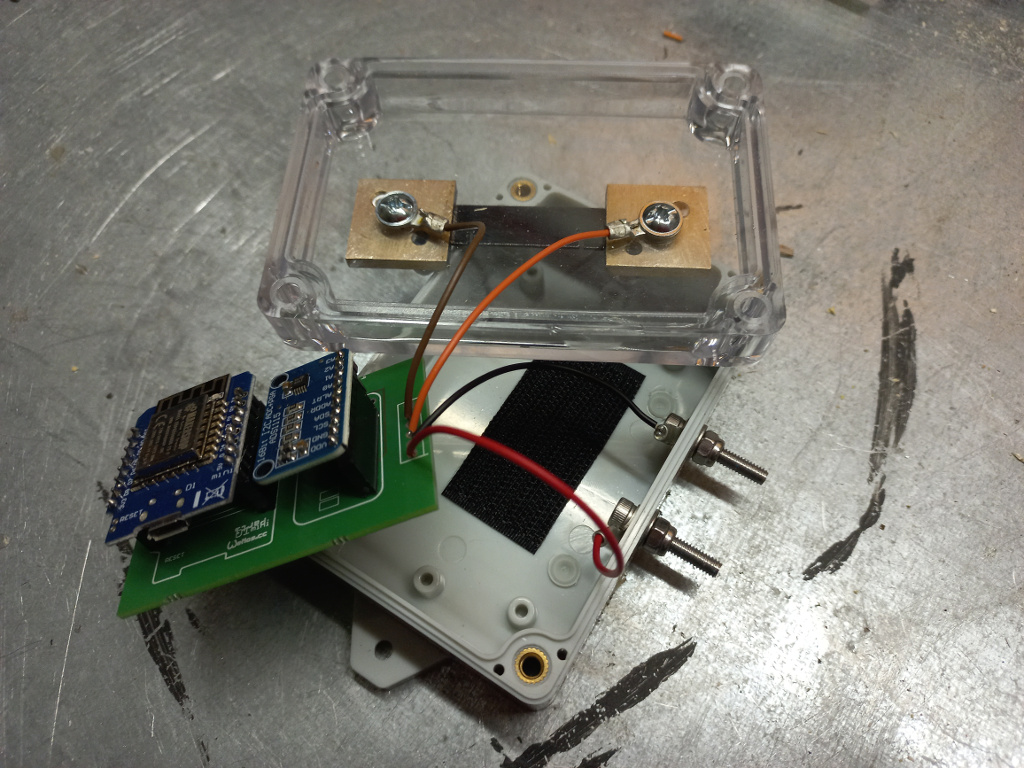
I use velcro strip to attach the circuit board. Again, I don’t have long-lasting experience on this but the installation is fast and so far the boards have remained in their places. Before attaching the strip I make sure the bottom of the circuit board is as flat as possible.
Attach the velcro strips.
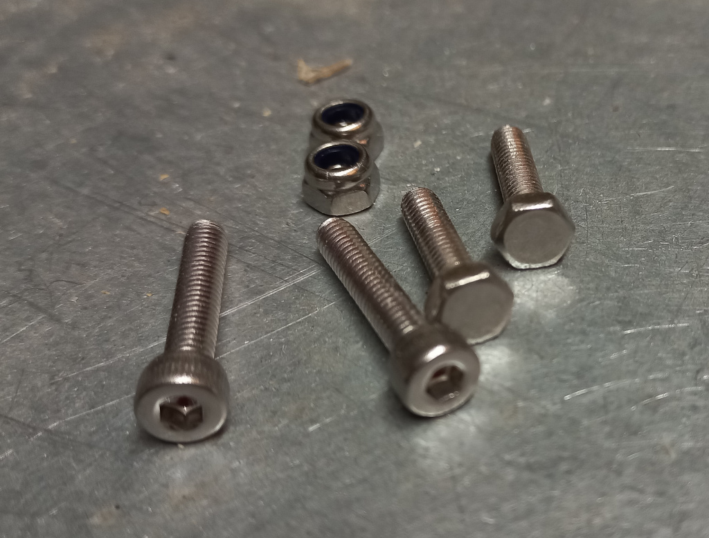
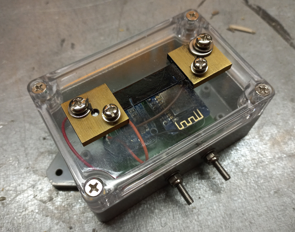
Now it is time install the connecting screws. I use hex screws as they can be fastened with a proper tool in 90 degree angle. Regular philips or torx screws would be problematic to hold inside the case. So far I haven’t used any sealant for securing the holes. All the nuts are nylock to avoid loosening connections.
Normally I avoid putting any connectors to the cover. This makes it easy to remove the cover to grab the microcontroller. In this current sensor I decided to install the shunt to the cover to make it easier to make load connection.
The sensor has four connectors.
- The screws on the shunt are for the load to be measured. If you’re not familiar with shunts take a look at this video.
- The two screws on the bottom are for powering the board (5V DC).
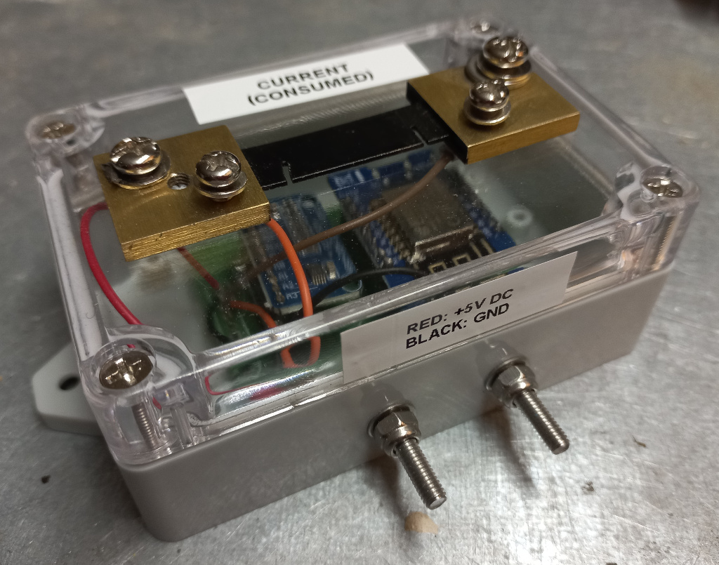
You yourself know what the particular sensor is by heart but if you care the future boat owners or engineers it is good idea to document the sensor and connectors.
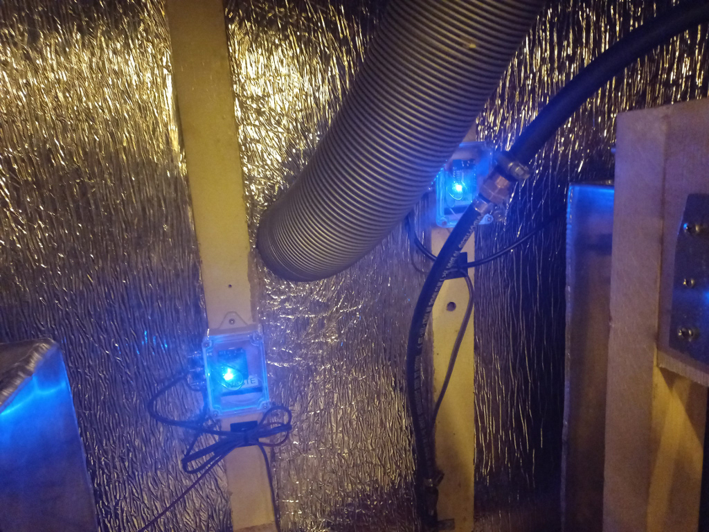
These two sensors are measuring the fuel and black water tanks. They use the ESP8266 internal ADC to measure the resistance of the gauges.