Here are brief instructions flashing TP-Link Archer MR600 v2 (EU) to OpenWRT. The PC used to flash is Debian-deriative Linux. You can use whatever TFTP to do this.
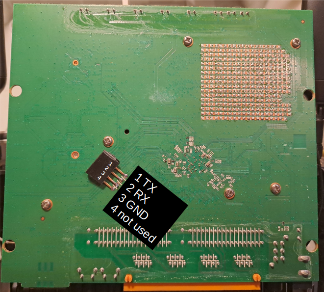
Unfortunately the MR600 stock firmware does not start TFTP recover without instructed from serial console. Thus, you have to connect your USB-TTL serial dongle as below:
Connect the router TX to your serial dongle RX, router RX to serial dongle TX and GND to GND. Set the serial speed to 115200 and disable the hardware flow control (if applicable).
Once you have the serial console you can continue to the flashing:
Power off the router and disconnect all ethernet cables except the one which is connected to your PC.
Set your ethernet IP to 192.168.0.5, netmask 255.255.255.0 (eth0 is my ethernet device):
sudo ifconfig eth0 192.168.0.5/24
Now you should be able to download the firmware file from your server:
curl -O tftp://192.168.0.5/test.bin
Make sure your serial console is now connected. Power the router up and press “t”, which should not give you the U-boot prompt:
4: System Enter Boot Command Line Interface.
U-Boot 1.1.3 (Feb 8 2021 - 16:37:49)
MT7621 #
Give command “tftpboot”. This should download the temporary kernel from your TFTP server.
MT7621 # tftpboot
Give command “bootm”. This should boot the downloaded image. Wait the kernel to boot and finally activate the device console. This should give you the OpenWrt logo and root command line:
## Booting image at 84000200 ...Now the OpenWrt kernel boots. Press enter to activate the device console:
BusyBox v1.36.1 (2025-02-03 23:09:37 UTC) built-in shell (ash)
  _______                     ________        __
 |       |.-----.-----.-----.|  |  |  |.----.|  |_
 |   -   ||  _  |  -__|     ||  |  |  ||   _||   _|
 |_______||   __|_____|__|__||________||__|  |____|
          |__| W I R E L E S S   F R E E D O M
-----------------------------------------------------
OpenWrt 24.10.0, r28427-6df0e3d02a
-----------------------------------------------------
=== WARNING! =====================================
There is no root password defined on this device!
Use the "passwd" command to set up a new password
in order to prevent unauthorized SSH logins.
--------------------------------------------------
root@OpenWrt:~#
Download the sysupgrade image. Again, you’ll find it from the device page.
If you cannot open the connection to the router, change your IP and netmask:
sudo ifconfig eth0 192.168.1.5/24
Finally, do the system upgrade by issuing the command in the router command line. You can do this by using the serial console or by connecting to the router via ssh (ssh root@192.168.1.1):
sysupgrade -v /tmp/sysupgrade.bin
After the router has rebooted you should be able to disconnect the ethernet cable and plug it in again. The router DHCP server should provide the IP settings to the PC.
Configuring
The default configuration has ethernet WAN port with three LAN ports. The configuration is straightforward:
Connect to the router using ethernet.
Log in to http://192.168.1.1 with empty password and set the root password.
Configure the wireless network (SSID and passkey) for 2,4 and 5 GHz.
Here are brief instructions flashing TP-Link Archer MR200 v5 to OpenWRT. The PC used to flash is Debian-deriative Linux. You can use whatever TFTP to do this.
Install TFTP server tftpd-hpa: sudo apt install tftpd-hpa
Get the latest firmware from OpenWRT firmware selector. At the time of writing 24.10.2 was the newest for MR200. You can find the correct firmware by using “mr200” as a search term. Download the “TFTP-RECOVERY” file.
Copy the downloaded file to TFTP server (make sure the final filename is “tp_recovery.bin”): sudo mv openwrt-24.10.2-ramips-mt76x8-tplink_archer-mr200-v5-squashfs-tftp-recovery.bin /srv/tftp/tp_recovery.bin
Make sure the TFTP server can read the file sudo chown tftp.tftp /srv/tftp/*
Power off the router and disconnect all ethernet cables except the one which is connected to your PC.
Set your ethernet IP to 192.168.0.225, netmask 255.255.255.0 (eth0 is my ethernet device): sudo ifconfig eth0 192.168.0.225/24
Now you should be able to download the firmware file from your server: curl -O tftp://192.168.0.225/tp_recovery.bin
Now power up the router while holding down WPS/Reset button for 10 seconds
After the router has rebooted you should be able to disconnect the ethernet cable and plug it in again. The router DHCP server should provide the IP settings to the PC.
Configuring
The default setup uses 4G modem as WAN interface. In my case I wanted to use the port 4 (WAN) as the WAN. Here is the procedure for this:
Connect to the router using ethernet.
Log in to http://192.168.1.1 with empty password and set the root password.
Configure the wireless network (SSID and passkey) for 2,4 and 5 GHz.
Now disconnect from the ethernet and reconnect using wireless. This may not be required but helped me while I was trying different ethernet settings.
Open ssh connection to the router: ssh root@192.168.1.1
Copy following content to /etc/config/network (may may scp the file or use the user-friendly editor “vi” to do the job):
The most useful and in-depth study has been carried out by OppoverBakke. In the first post he studies the power use of ESP8266 and in the second one he suggests the correct order of WiFi.forceSleepWake() and WiFi.mode() calls. The yield() call is required to let ESP ROM to get its internal things straight.
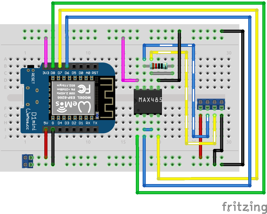
This brief note explains how to connect ESP8266 and Peacefair PZEM-017 to read voltage and current from the sensor over Modbus RTU (the RS485 based serial protocol).
Building a microcontroller based sensor for my yacht appeared to be an easy task. During last year I have learned a lot and thought it would be nice to share some ideas.
From InfluxDB to SignalK
My initial choice for an architecture was InfluxDB. It appeared to offer everything you would want:
Installable as an Docker image
Lightweight enough to run on Raspberry Pi
A large variety of diagrams to choose from
Library to ESP8266 (Wemos D1 mini)
At this point the SignalK server and SensESP looked like too complicated and bloat for me. However, after following my tinkering for the first season my co-founder wanted something more professional-looking. He was also worried that a 100% DIY project would be a problem when we had to look for a new owner to our boat.
It took me a while to get myself familiar with the aforementioned framework. I even tried to write my own implementation of the SignalK client for ESP8266. Finally I gave up and did a showcase of some SensESP sensors producing random values and SignalK server with the default Instrument Panel. That did the trick.
Finding a Decent Case
Building the first sensors on the breadboard was an easy task but finding a decent case was harder than you could think. After playing with the first prototypes I came up with the following list of requirements:
The case should be waterproof(ish) and durable enough to survive the marine life. Our engine room is theoretically dry but there is always moisture on the boats.
No rusting metal parts. The screws (if any) should be plastic or stainless steel.
There should mounting lugs for wall mounting. It is not acceptable to mount the sensor by drilling the through its bottom as the circuit board must be removed to access the holes/screws.
There should be enough space for connectors.
No matter how nice over-the-air updates you might have at least I definitely have to have an easy access to the microcontroller. The housing should be easily opened.
Clear case would show the LED signals and help troubleshooting the sensors.
As we’re communicating on wifi it is best to avoid aluminium cases.
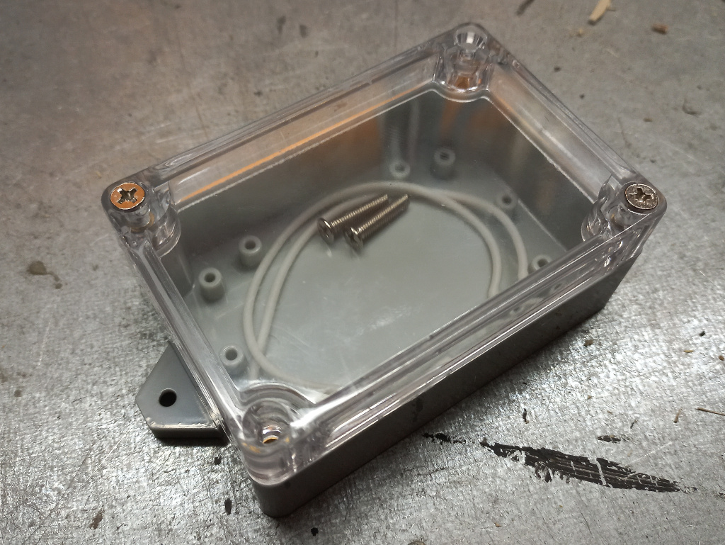
I tried to find a proper housing from the local electronics webshops and purchased some promising cases. Typically the screws securing the cover were in the bottom. In the prototype (well, it was supposed to be a production version but…) shown in the picture the I replaced the original screws with stainless steel threaded rods and nylock nuts. It worked all right but was a bit too laborious.
An early prototype with 4-channel ADS1115 voltage meter.
Finally I managed to find cases I had been looking for. I ordered one larger and one smaller box for and start. It turned out that they satisfied all my requirements.
Powering the Board
My first idea about powering the sensors was to build a old-school voltage regulator LM7805 in each of the devices (see this blog post for an example). With this I could use the yacht’s 24V DC and possibly avoid some wiring.
However, I soon found out that this cause me a lot of work and increased the risk for mistakes in soldering. I actually fried some capacitors when making this!
The next level in this path was to order an adjustable voltage regulator component from Asia. I bought a bag of these from Aliexpress but they turned out to be crap. Or maybe I could not install them, you never know.
These setbacks made me think of alternatives. I had noticed that still engineered a 24 V power cable to each of the sensors so I could power off the devices if required. My hope of somewhat utilising the existing power cables did not prove to work. Distributing the 24-to-5 DC-DC step-down made the sensors more compilated, large and prone to errors than installing the 5 V power network for the sensors.
Finally I ordered a DIN rail installable DC-DC converter which gave me a stable five volts. It even has short circuit protection which has saved me a couple of times.
Connectors
In the very first experiments I drilled a hole to the housing and connected the wires to screw terminals on the board. While my goal was build the sensor at home and spend minimal time onboard installed the screw terminals outside the housing as can be seen in the early prototype above. This proved to be functional but required manual steps which I wanted to avoid. You have to drill holes for wires and screws securing the terminal bar and use a silicone to seal the holes. Especially the latter was time-consuming and messy.
I tried to find waterproof connectors which I could use but they turned out to be hard to find. As I wanted to housing cover to be as removable as possible without any wirings the connector should be small enough to be installable to the bottom part of the box. Again, if I had connectors to gauge and power I would need two connectors which would mean more soldering and drilling. I would have to solder tiny connectors onboard which I wanted to avoid as much as possible.
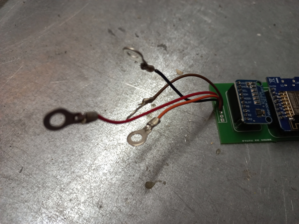
My current solution is to use stainless steel screws going through the housing. The wires both inside and outside have ring terminals. To secure the connection I solder all connectors to their wires.
While I don’t have long lasting experience of the solutions it appears to be quite nice at least to install. The Abiko connectors are widely available, robust and easily installable onboard. The screw terminals allow me to attach multiple wires to them. I can chain the power lines from sensor to another or use common ground or power for sensor and gauge (e.g. the Hall sensor for revolution measurement).
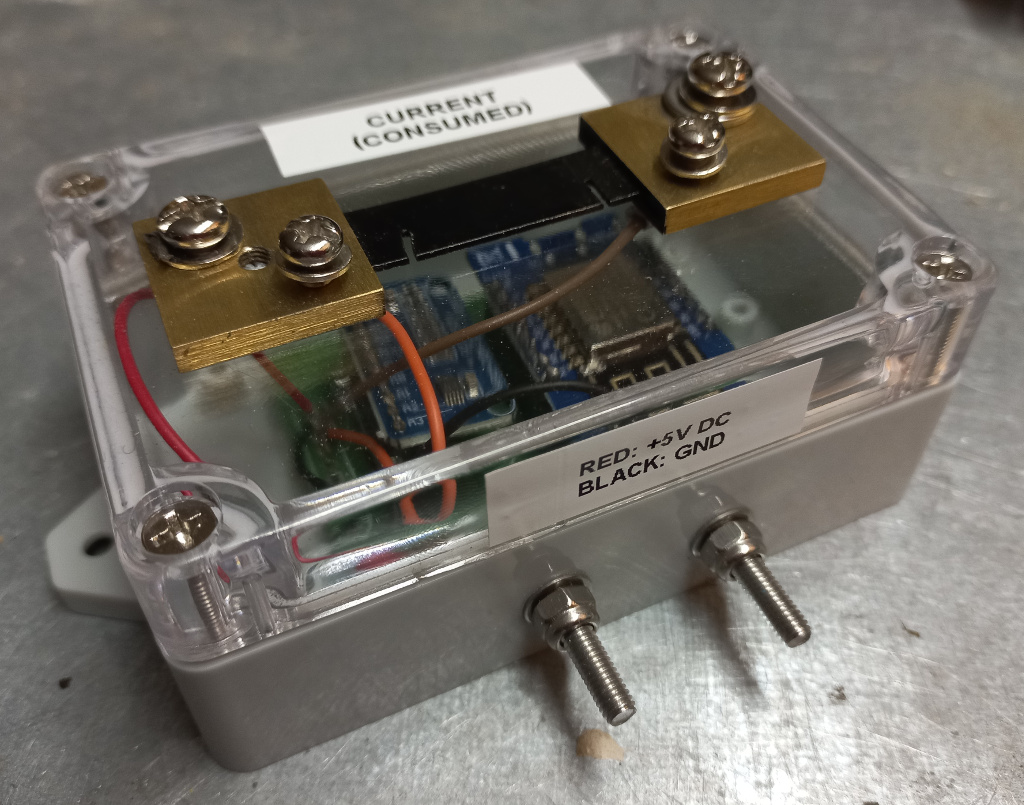
Building a Current Sensor
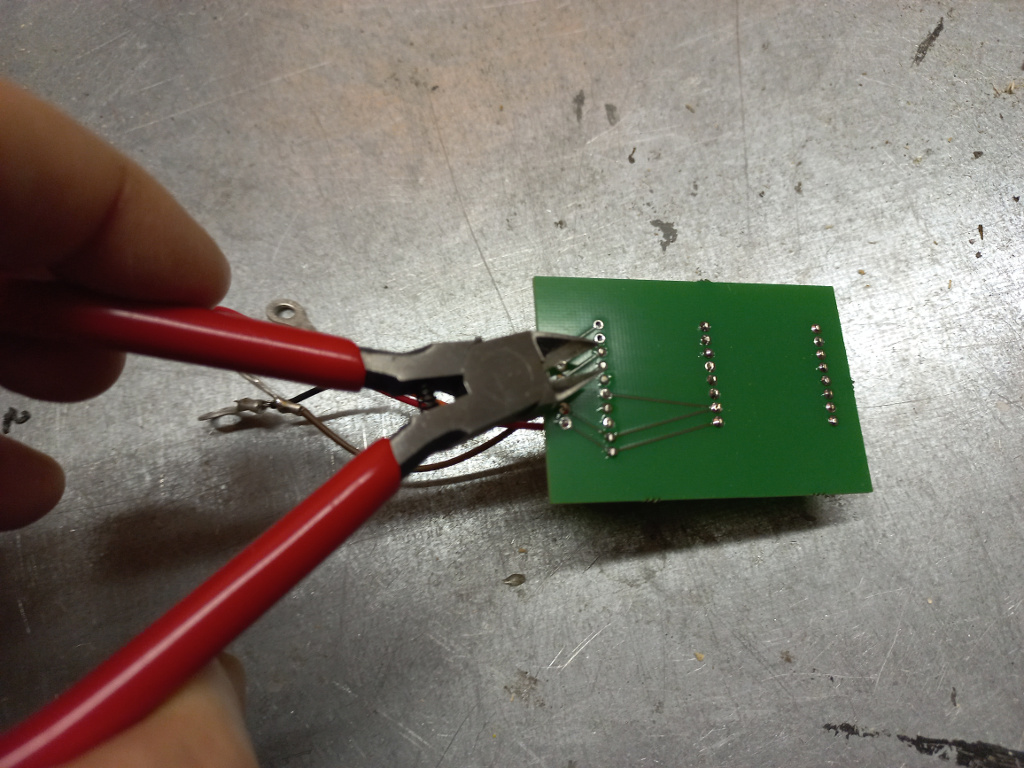
In this example I’m building a case for a current sensor. It has Wemos D1 mini with ADS1115 powered by SensESP firmware. The circuit board is made by Aisler. I have made sensors with prototyping board but again, there are a lot of soldering and tinkering which may break in the marine environment. While the Aisler prices are ridiculously low I wonder why bother.
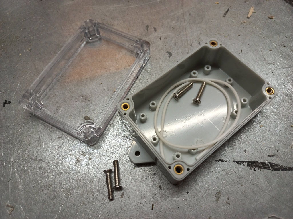
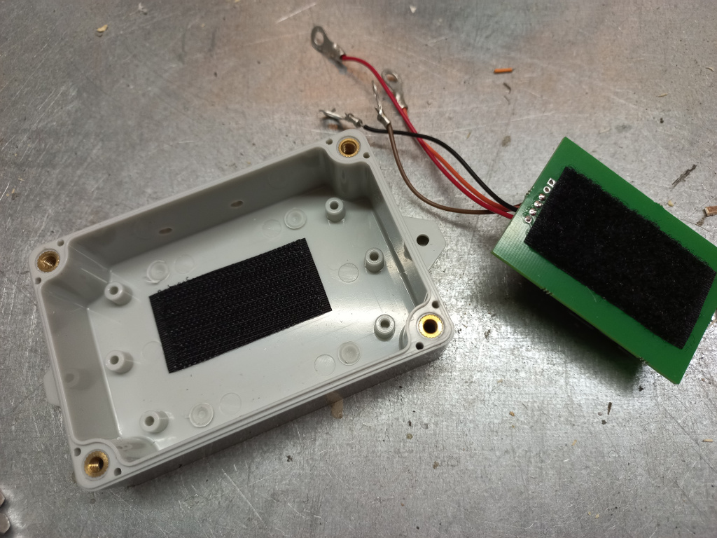
The abovementioned cases look looks this. The white strip is for making the case waterproof. There is a groove on the cover for this.
All the wires connecting to the circuit board have ring terminals. The wires are soldered to the board. I avoid using screw terminals to avoid the risk of loosening connections.
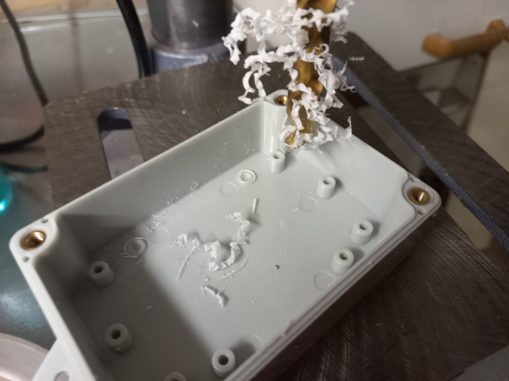
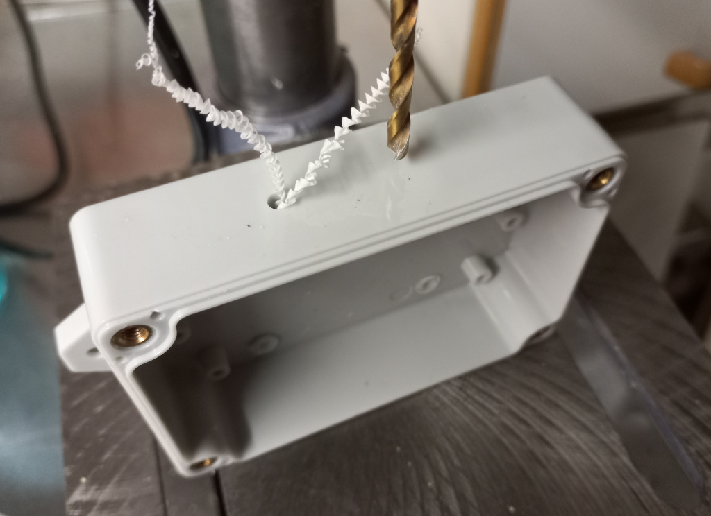
The housing has seats for the screws. As I don’t need them I drill them away.
Drilling holes for the connector screws. I use 4 mm drill for M4 screws.
I use velcro strip to attach the circuit board. Again, I don’t have long-lasting experience on this but the installation is fast and so far the boards have remained in their places. Before attaching the strip I make sure the bottom of the circuit board is as flat as possible.
Attach the velcro strips.
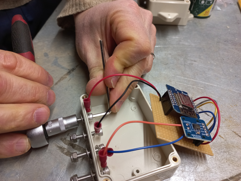
Now it is time install the connecting screws. I use hex screws as they can be fastened with a proper tool in 90 degree angle. Regular philips or torx screws would be problematic to hold inside the case. So far I haven’t used any sealant for securing the holes. All the nuts are nylock to avoid loosening connections.
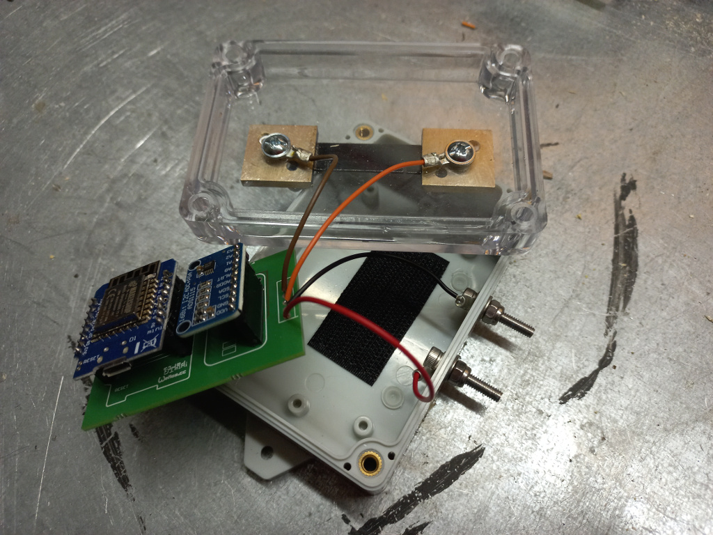
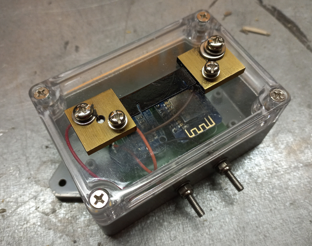
Normally I avoid putting any connectors to the cover. This makes it easy to remove the cover to grab the microcontroller. In this current sensor I decided to install the shunt to the cover to make it easier to make load connection.
The sensor has four connectors.
The screws on the shunt are for the load to be measured. If you’re not familiar with shunts take a look at this video.
The two screws on the bottom are for powering the board (5V DC).
You yourself know what the particular sensor is by heart but if you care the future boat owners or engineers it is good idea to document the sensor and connectors.
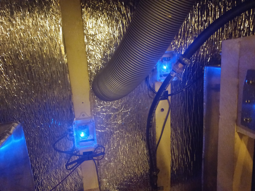
These two sensors are measuring the fuel and black water tanks. They use the ESP8266 internal ADC to measure the resistance of the gauges.
It took me a while to find out how to connect MAX6676 to Wemos D1 to read temperature. Many references suggested to use Wemos D1 pins D6-D8 but this fails. Following pinout works:
D5 – SCK
D6 – CS
D7 – S0
Here is the sample code with correct pin definitions:
/*
  Average Thermocouple
  Reads a temperature from a thermocouple based
  on the MAX6675 driver and displays it in the default Serial.
  https://github.com/YuriiSalimov/MAX6675_Thermocouple
  Created by Yurii Salimov, May, 2019.
  Released into the public domain.
*/
#include <MAX6675_Thermocouple.h>
#include <Thermocouple.h>

#define SCK_PIN D5
#define CS_PIN D7
#define SO_PIN D6

Thermocouple* thermocouple;

// the setup function runs once when you press reset or power the board
void setup() {
  Serial.begin(9600);

  thermocouple = new MAX6675_Thermocouple(SCK_PIN, CS_PIN, SO_PIN);
}

// the loop function runs over and over again forever
void loop() {
  // Reads temperature
  const double celsius = thermocouple->readCelsius();
  const double kelvin = thermocouple->readKelvin();
  const double fahrenheit = thermocouple->readFahrenheit();

  // Output of information
  Serial.print("Temperature: ");
  Serial.print(celsius);
  Serial.print(" C, ");
  Serial.print(kelvin);
  Serial.print(" K, ");
  Serial.print(fahrenheit);
  Serial.println(" F");

  delay(500); // optionally, only to delay the output of information in the example.
}
After installing the ESPhome firmware to my SH-P01s I quickly noticed I had to update the firmware settings. It turned out that updating the firmware is easy after the device is running on ESPhome.
First I had to find out the IP of the device. I used nmap for this. First I connected my laptop to the same network with the relays and then:
$ nmap -sL 192.168.4.0-255

Starting Nmap 7.60 ( https://nmap.org ) at 2020-02-24 22:11 EET
Nmap scan report for 192.168.4.0
Nmap scan report for 192.168.4.1
….
Nmap scan report for 192.168.4.30
Nmap scan report for relay_1.your.localdomain (192.168.4.31)
Nmap scan report for 192.168.4.32
…
Nmap scan report for 192.168.4.58
Nmap scan report for relay_2.your.localdomain (192.168.4.59)
Nmap scan report for 192.168.4.60
…
Nmap scan report for 192.168.4.255
Nmap done: 256 IP addresses (0 hosts up) scanned in 0.32 seconds
It was easy to find the relay 1 and its IP 192.168.4.31 from the nmap output. Now I could edit the firmware configuration and re-compile the firmware. I used the dockerised version of ESPhome:
docker run --rm -v "${PWD}":/config -it esphome/esphome relay_1.yaml upload --upload-port 192.168.4.31

INFO Reading configuration relay_1.yaml…
INFO Connecting to 192.168.4.31
INFO Uploading relay_1/.pioenvs/relay_1/firmware.bin (428624 bytes)
Uploading: [============================================================] 100% Done…

INFO Waiting for result…
INFO OTA successful
INFO Successfully uploaded program.
Note! This document is not validany more. The SH-P01 devices I purchased on late 2021 were running a patched firmware. Thus, the Tuya-convert is not able to flash the SH-P01s.
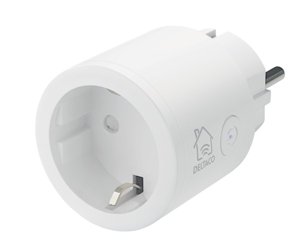
This is a documentation of a ongoing work where I’m trying to get Deltaco Smartplug SH-P01 to work with Home Assistant.
Since the Home Assistant does not have a native support for the device I’m planning to:
Create an ESPhome firmware with the configuration I found from the Home Assistant discussion board
Since I already had Docker installed on my laptop I entered
docker pull esphome/esphome
and got the ESPhome Docker image. After this I created relay_1.yaml with following content:
esphome:
  name: relay_1
  platform: ESP8266
  board: esp01_1m

# Your WiFi SSID and passphrase is defined here
# https://esphome.io/components/wifi.html
wifi:
  ssid: "YOUR_WLAN_SSID"
  password: "YOUR_WLAN_PASSPHRASE"

# Enable fallback hotspot (captive portal)
# In case the device can't connect the host defined above
# it starts to work as an access point with these settings
# https://esphome.io/components/captive_portal.html
  ap:
    ssid: "Smartplug Deltaco 1"
    password: "RANDOM_PASSWORD_NEEDED_IN_CASE_THE_DEVICE_CANT_CONNECT_WLAN"

captive_portal:

# Enable logging
logger:

# Enable Home Assistant API
# https://esphome.io/components/api.html
api:
  password: "RANDOM_PASSWORD_FOR_HOME_ASSISTANT_TO_CONNECT"

# Enable Over The Air update component
# https://esphome.io/components/ota.html
ota:
  password: "RANDOM_PASSWORD_FOR_ESPHOME_OTA_UPDATES"

binary_sensor:
  - platform: gpio
    pin:
      number: GPIO13
      mode: INPUT_PULLUP
      inverted: True
    name: "Deltaco SH-P01 Button"
    on_press:
      - switch.toggle: deltaco_relay_1
  - platform: status
    name: "Deltaco SH-P01 Status"

output:
  - platform: esp8266_pwm
    id: deltaco_smartplug_blue_led
    pin:
      number: GPIO5
      inverted: True

switch:
  - platform: gpio
    name: "Deltaco SH-P01 Relay"
    id: deltaco_relay_1
    pin: GPIO12

light:
  - platform: monochromatic
    name: "Deltaco SH-P01 blue LED"
    output: deltaco_smartplug_blue_led
This was taken from the discussion board referred above. All I needed to do was to edit the SSIDs and passwords and compile a new firmware:
docker run --rm -v "${PWD}":/config -it esphome/esphome relay_1.yaml compile
This printed a lot of debug information and ended with following lines:
Building .pioenvs/relay_1/firmware.bin
 Retrieving maximum program size .pioenvs/relay_1/firmware.elf
 Checking size .pioenvs/relay_1/firmware.elf
 DATA:    [=====     ]  45.3% (used 37148 bytes from 81920 bytes)
 PROGRAM: [====      ]  41.5% (used 425048 bytes from 1023984 bytes)
 Creating BIN file ".pioenvs/relay_1/firmware.bin" using ".pioenvs/relay_1/firmware.elf"
 ========================= [SUCCESS] Took 29.83 seconds =========================
 INFO Successfully compiled program.
And yes, the compiled firmware was at .esphome/build/relay_1/.pioenvs/relay_1/firmware.bin! All I needed to do is to get this firmware to the device.
Flashing the Firmware with tuya-convert
The tuya-convert offers a docker image to make the flashing, but I could not make it work. Therefore I installed the script and required packages directly to my Ubuntu as instructed in the README:
git clone https://github.com/ct-Open-Source/tuya-convert
cd tuya-convert
nano -w config.txt
# Changed value WLAN to my device name, wlx7cdd901255af
# Enumerate your device names with "ifconfig"
sudo ./install_prereq.sh
At this point I disconnected by WLAN from the local access point so it was available for tuya-convert. I also copied the ESPhome firmware.bin to tuya-convert/files/relay_1.bin. Then it was time to start the flashing script:
sudo ./start_flash.txt
When instructed I joined my phone to new WLAN access point “vtrust-flash” and after this was done I reset my SH-P01. It took me a while to understand why it did not respond when I pressed the button for the magic 6 seconds. Finally it turned out that the device already had connected to the AP.
The script did the trick. First it downloaded the firmware backup and after that it asked which binary file I wanted to install. After a while the relay_1.bin was uploaded.
Installing Home Assistant
Since I have a Xen server I installed the Home Assistant to a fresh VM running Debian Stretch. The Home Assistant configuration was quite uneventful as everything went as planned.
Since the server and the SH-P01 were on the same network segment (same LAN) the switch was discovered right away. All I needed to do was to give the API password I defined in relay_1.yaml and wrote to the ESPhome firmware.
Everything worked: the relay, the light and the button.
Flashing More Devices
To add more devices just make a copy of the ESPhome configuration (relay_1.yaml) and edit the esphome:name -setting:
The device names must be unique and they’re used for example as a hostname of the device. Home Assistant creates its ID:s from device names (e.g. “Deltaco SH-P01 Relay” becomes “switch.deltaco_sh_p01_relay”). In case you’re worried about these entity ID:s you might want to give distinctive names to avoid overloading (“switch.deltaco_sh_p01_relay_2”, “switch.deltaco_sh_p01_relay_3” etc.). You might also want to change some of the passwords. After this just repeat the steps with the new firmware.
The sample configuration toggles the relay when the button is pressed. If you don’t want this behaviour but want to control the relays by the Home Assistant automations just remove this codeblock:
Some notes in the net suggest that you should set the TimeoutSec=infinity in the systemd configuration, but this did not help in my case. I had to disable the AppArmor for /usr/sbin/mysqld. It wasn’t enough to put it to complain mode. Here are the instructions:
Get apparmor-utils
If you can’t execute “sudo aa-disable” you have to install the AppArmor utilities:
sudo apt install apparmor-utils
Create AppArmor profile for MariaDB
By default the AppArmor profile for /usr/sbin/mysqld is empty which causes “aa-disable” to fail. Add following lines to “/etc/apparmor.d/usr.sbin/mysqld”:
The job was pretty straight-forward: change the keyboard combinations in the file.
Keycodes
The idea of xkb file is to translate keycodes to characters. The first step is to identify the keys in the keyboard. Each key produces its own keycode. For a start I used Figure 2 in this documentation to get an idea ofo the keycodes. However, my keyboard layout (and the documented Sami layout) differed from fig 2.
To get a keycode for a key:
$ xev -event keyboard

KeyRelease event, serial 28, synthetic NO, window 0x2200001,
 root 0x12d, subw 0x0, time 85909731, (-350,-52), root:(244,267),
 state 0x0, keycode 38 (keysym 0x61, a), same_screen YES,
 XLookupString gives 1 bytes: (61) "a"
 XFilterEvent returns: False
The xev utility gives you the keycodes but this code cannot be used as such in your xkb definitions where the keys are identified with a hex tuplet (e.g. AC01) or a tag (e.g. LSGT). To get your xkb-compliant key identifier:
Wow! Now I know that A in my keyboard -> keycode 38 -> AC01 in xkb definition.
Characters not defined in keysymdef.h
Most of the xkb howtos I browsed explained that all the symbols are defined in the keysymdef.h. Well, that wasn’t the case with Sami characters. Instead of using the defined keyboard symbols I had to use Unicodes. Say we want to implement Đ character.
If possible, try to get the character to a clipboard. I ended up using Windows implementation to get all three different hyphens right.
Get the Unicode code point (for Đ it is U+0110) which can be used in the xkb definition (“U0110”).
When implementing my second keyboard layout I found a search tool which helped me a lot in finding exotic characters. Workflow:
Start a Windows with selected keyboard layout in a virtual machine. Start a Notepad.
Push a key to see what character appears to the notepad. Copy and paste it to search tool.
The Unicode number can be entered directly to the keyboard definition but I tried to find the symbol from the keysymdef.h whenever I could. It makes keyboard definition file more readable.
Repeat with Shift+Key, AltGt+Key and Shift+AltGr+Key.
VoidSymbol
To avoid strange characters appear when you type the undefined combinations use “VoidSymbol”. So if you define keys like this:
 key <AC01> { [ a, A ] };
 key <AC02> { [ s, S ] };
and press AltGr+A or AltGt+Shift+S you might get some random characters To avoid these chars use VoidSymbol to make sure that no definions are inherited (or whatever neat feature causes this):
 key <AC01> { [ a, A, VoidSymbol, VoidSymbol ] };
 key <AC02> { [ s, S, VoidSymbol, VoidSymbol ] };